Permanent magnet rotor e1655961736623.jpeg.
For high-speed permanent magnet machines (HSPMMs), two different rotor structures are widely used: surface-mounted permanent magnet (SPM) and interior permanent magnet (IPM). The two different rotor structures have a large impact on the comprehensive performance in multiple physical fields of HSPMMs, including mechanical …
1,416 permanent magnets stock photos, 3D objects, vectors, and illustrations are available royalty-free. See permanent magnets stock video clips. Experimental electric generator on white background, consists of copper coils and magnets. A generator is a device that converts mechanical energy to electrical energy for use in an external circuit. Today’s automotive industry has focused its studies on electric vehicles (EVs) or hybrid electric vehicles (HEVs) rather than gasoline-powered vehicles. For this reason, more investment has been made in electric motors with high efficiency, high torque density, and high-power factor to be used in both EVs and HEVs. In this study, an outer-rotor …Aug 17, 2022 · For high-speed permanent magnet machines (HSPMMs), two different rotor structures are widely used: surface-mounted permanent magnet (SPM) and interior permanent magnet (IPM). The two different rotor structures have a large impact on the comprehensive performance in multiple physical fields of HSPMMs, including mechanical stress, electromagnetic characteristics, and temperature distribution ... Jan 8, 2021 · The permanent magnet is axially magnetized; meaning that the north and south poles alternate and are on the same axis as the motor shaft. When current is applied to windings, poles on the stator are magnetized and align with the opposite poles from the permanent magnet rotor. For example, north poles would align directly across from south poles. Recently, PMSMs having high power density and high efficiency are widely used in premium home appliances and electric vehicles. 1 Compared to a SPMSM (surface-mounted permanent magnet synchronous motor), large torque ripple in an IPMSM is a bad influence on the system in a variable speed range. 2 The optimization of a motor is …
A permanent magnet rotor assembly is a crucial component in various applications, including BLDC motors, generators, and magnetic couplings. It consists of a rotor with permanent magnets, such as neodymium magnets, mounted on it to ensure an efficient and reliable magnetic field generation. The interaction between the magnetic field …When considering the mechanical design of these rotors, SPM rotors allow higher rotational speeds than IPM rotors and will be the focus of this article. The …This paper proposes a new design method for sleeve thickness and interference based on a multi-dimensional visualization algorithm that overcomes difficulties in solving. The contact pressure between the rotor core and the permanent magnet, the maximum equivalent Mises stress of the permanent magnet, and the maximum …
2.1 Electrical Characteristics. The equivalent circuit of a PMDC motor is shown in Fig. 1. The supply voltage and the current are given. The circuit consists of an induced voltage (Vi) in series with an armature resistor (Rarm) and inductance (Larm). The rotation of the ux generates the induced voltage.
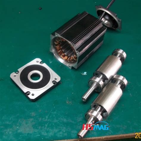
The rated power and speed of the permanent magnet grinding electric spindle are 7.5Kw and 950r/min, respectively.The main parameters of the PMGES are as follows, the rotor mass is m = 5.66 kg; the rotor radius is R = 0.072 mm; the axial length of the air gap is L = 0.178 mm, nominal air gap length is δ 0 = 3 × 10 −3 m, air permeability …A high-speed (HS) permanent magnet (PM) synchronous motor (HSPMSM) with a carbon fiber-reinforced plastic (CFRP) protective sleeve in the surface-mounted rotor was explored in this study.More specifically, the rotor itself contains permanent magnets, which are either surface-mounted to the rotor lamination stack or embedded within the rotor …When the rotor magnets are placed inside the rotor iron in PMSM, the machine is called interior permanent magnet (IPM) . In this case, the magnetic reluctance is not uniform as it was for SM-PMSM. So, the self-inductance value of the stator will depend on the rotor position and, consequently, there will be nonzero reluctance torque in addition to the …This paper proposes a novel layered permanent magnet motor (N-LPM), which is based on a three-degree-of-freedom (3-DOF) permanent magnet motor. Compared with the former, the improved N-LPM air gap magnetic density, torque and structure stability have been significantly improved. The proposed N-LPM has three …
The development of high-speed (operating at a rotation speed above 10,000 rpm) synchronous electric machines with permanent magnets is currently a relevant design direction [1,2,3,4,5].The structure of the rotor of synchronous machines with permanent magnets is a system of permanent magnets kept from their radial movement with the …
Dec 15, 2023 · Interior permanent magnet (IPM) motors in traction applications often employ discrete rotor skewing constructions to reduce torsional excitations and back-EMF harmonics. Although skewing is very effective in reducing cogging torque, the impact on torque ripple is not well understood and can vary significantly over the operating envelope of a motor. Skewing also leads to the creation of a non ...
1,417 permanent magnets stock photos, 3D objects, vectors, and illustrations are available royalty-free. See permanent magnets stock video clips. Experimental electric generator on white background, consists of copper coils and magnets. A generator is a device that converts mechanical energy to electrical energy for use in an external circuit.The advantages of choosing Sintex® magnetic rotors are as follows: Patented solutions. Complete solutions. 100% sealed enclosure – can run as wet runner. Corrosion-resistant materials. High efficiency / low energy loss. Maintenance-free. Long service life. …1. Introduction. At present, the low-speed high-torque transmission system has vast application prospects in the application fields of ship propulsion, lifting, mining and oil field exploitation [1].Permanent magnet motors can maintain good performance in a wide range of load changes, so they have received extensive attention in low-speed and large …Apr 8, 2022 · This paper proposes two structures of dual-stator permanent-magnet vernier machines (VMs) for high-torque low-speed applications. The proposed structures consist of dual-sided rotor which is sandwiched by inner and outer stators. These topologies include 22 and 46 consequent-pole magnets in the rotor and 24 and 48 stator slots for Design A and Design B, respectively. Design A is an improved ... The prototype machine is an axial-flux permanent-magnet machine with a two-rotor–one-stator configuration. The nominal power of the machine is 300 W and the nominal rotational speed is 500 rpm. The magnets are neodymium iron boron magnets. Twelve magnets are mounted on the rotor surface and 12 magnets buried on the rotor (Fig. 12a).Our permanent magnet rotor assembly, designed for use in brushless DC (BLDC) motors, generators, and more, are built with the highest quality materials, including neodymium …
Feb 9, 2018 · Electric machines with permanent magnet rotors are becoming increasingly popular due to the high power density that they offer relative to other configurations. Where the speed of rotation is high, the magnets are typically mounted on the surface of the rotor and retained by an outer sleeve. In the literature, a variety of analytical models have been proposed to aid the mechanical design ... A commercial traction motor (Prius 2010), designed with Nd-Fe-B magnets for maximum power 60 kW and maximum speed 13,500 rpm, is used as the baseline for comparing the HRMM design. The HRMM design shows comparable performance with the commercial design for the given speed range with ~ 50% reduction in critical rare earth …2.1 Electrical Characteristics. The equivalent circuit of a PMDC motor is shown in Fig. 1. The supply voltage and the current are given. The circuit consists of an induced voltage (Vi) in series with an armature resistor (Rarm) and inductance (Larm). The rotation of the ux generates the induced voltage.A Permanent Magnet DC motor (PMDC motor) is a type of DC motor that uses a permanent magnet to create the magnetic field required for the op...When considering the mechanical design of these rotors, SPM rotors allow higher rotational speeds than IPM rotors and will be the focus of this article. The …
As shown, it mainly consists of permanent magnet rotor (PMR) and conductor rotor (CR). The CR is composed of two rotors, each of which contains copper sheet (CS) and corresponding back iron. The PMR is divided into flux-adjustable rotor (FAR) and fixed flux rotor (FFR), each of which adopts spoke-mounted PMs magnetized …
As high-performance motors, permanent magnet motors are widely used in a wide range of applications. It has become a consensus to mine reluctance torque in permanent magnet motors. The combination of permanent magnet motors and reluctance motors to generate higher output torque is one of the hotspots in motor research. A dual …Measure Skewing Angle. MagScope software makes it easier than ever to measure the skewing angle of skewed permanent magnet rotors, enabling the detection of skewing angle deviations. The right figure shows an example of the step skew on an IPM (Interior Permanent Magnet) rotor, represented in a cross-section graph with automatic zero-crossing ... 2.1 Electrical Characteristics. The equivalent circuit of a PMDC motor is shown in Fig. 1. The supply voltage and the current are given. The circuit consists of an induced voltage (Vi) in series with an armature resistor (Rarm) and inductance (Larm). The rotation of the ux generates the induced voltage.In order to improve the performance of synchronous motors, especially in dynamic-transient conditions, induction damper cages are usually used in the rotor structure. In this paper, a new hybrid structure of an axial-flux motor is proposed, which uses a permanent magnet (PM) rotor and an unpaired induction damper cage with …Permanent-magnet fields are, by definition, constant and not subject to failure, except in extreme cases of magnet abuse and demagnetization by overheating. Although PM motors are more expensive than induction motors, they offer a longer operating life, improved efficiency, better thermal resistance, reduced size and weight.Mar 20, 2021 · Reluctance is a function of rotor position in a variable reluctance motor. Sequential switching (Figure below) of the stator phases moves the rotor from one position to the next. The mangetic flux seeks the path of least reluctance, the magnetic analog of electric resistance. This is an over simplified rotor and waveforms to illustrate operation. high efficiency motors with power-dense permanent magnet rotor materials Arnold manufactures Recoma® 35E, the world’s most power-dense samarium cobalt material available on the market today. This innovative magnetic material is critical to boosting performance in the aerospace, automotive and motorsport industries, providing superior …
Nov 11, 2021 · According to the location of permanent magnet on the rotor, the permanent magnet synchronous motor rotor mainly has two different structures: surface-mounted and buried. Due to the strength limitation of silicon steel sheets, the application of buried rotor in the high-speed field is relatively smaller than surface-mounted rotor.
A permanent magnet is a material that can provide magnetic flux when magnetized with an applied magnetic field and its magnetism capability is characterized by two key parameters: remanence and coercitivity. In general, the intrinsic coercitivity of a permanent magnet (Hcj ) is greater than 300kOe (in the CGS unit) or 24kA / m (in the SI unit).
The windings of coreless axial flux permanent-magnet machine (CAFPM) are exposed to the rotor magnetic field, where each back electromotive force (EMF) harmonic is induced not only by several ...Rotor The rotor is made of permanent magnet and can vary from two to eight pole pairs with alternate North (N) and South (S) poles. Based on the required magnetic field density in the rotor, the proper magnetic material is chosen to make the rotor. Ferrite magnets are traditionally used to make permanent magnets. As the technology advances, rare In this work we proposed to study the use of permanent magnet synchronous motors (PMSM) for railway traction in the high-speed trains (HST) of Renfe Operadora (the Spanish national railway operator). Currently, induction motors (IM) are used in AVE classes 102–112 trains, so, the IM used as a traction motor in these trains has …high efficiency motors with power-dense permanent magnet rotor materials Arnold manufactures Recoma® 35E, the world’s most power-dense samarium cobalt material available on the market today. This innovative magnetic material is critical to boosting performance in the aerospace, automotive and motorsport industries, providing superior …Dec 1, 2017 · In their work, a range of electric machine options are considered and it is concluded that a synchronous machine with a permanent magnet (PM) rotor will be the most efficient and power dense. In addition to applications in turbocharging, Gerada [ 3 ] highlight an increasing demand for high-speed electrical machines in flywheel energy storage ... For the high-frequency permanent magnet electrical machine, a reasonable mechanical aspect design is crucial to meet its stability and reliability. This study focuses on the accurate modelling and analysis of the natural frequencies and modes of the rotor assembly for a designed and manufactured 100 kW 32,000 r/min motor.The main objective of this paper is to design and analyze the performance of in-wheel outer rotor permanent magnet synchronous motor (PMSM) used in electric vehicles based on a previously designed ...Magnetization process for PM rotors. The Permanent Magnet (PM) motor is a critical part in many electric car powertrain designs, which is undergoing rigorous improvement and changes. PM motors offer compact design and higher system efficiency among other advantages. The race for the electric cars has begun in the automotive industry and ... Permanent-magnet motors can be designed to operate at synchronous speed from a supply of constant voltage and frequency. The magnets are embedded in the rotor iron, and a damper winding is placed in slots in the rotor surface to provide starting capability. Such a motor does not, however, have means of controlling the stator power factor. Permanent Magnet Rotors High-Speed, High-Reliability, High-Efficiency Permanent Magnet Rotors For over 25 years, Integrated Magnetics has developed and refined the …This study proposes design procedures for the permanent-magnet-biased magnetic bearings (PEMBs) in rotor systems. Many aspects of designing magnetic …
2 Rotor system dynamics modelling of high-speed PM motor 2.1 Support characteristics of active magnetic bearings (AMBs) To make the rotor reach a high speed, the use of non-contact magnetic bearing or air bearing is required. First the rotor critical speed analysis needs to study the support characteristics of rotor-bearing system.Yu S B, Tang R. Electromagnetic and mechanical characterizations of noise and vibration in permanent magnet synchronous machines. IEEE Trans Magn, 2006, 42: 1335–1338. Article Google Scholar Zuo S, Lin F, Wu X. Noise analysis, calculation, and reduction of external rotor permanent-magnet synchronous motor.the permanent magnet Once the permanent magnet is inserted into a slot of the rotor core, it generates a stress-point within the core as a result of centrifugal force. If the permanent magnet slips out of the slot within the rotor core during operation of the drive motor as a result of this centrifugal force, the permanent magnet, the rotor core, or …Aug 5, 2020 · To enhance the torque density of a permanent magnet (PM) motor, a rotor overhang structure (OS), which is a simple and effective way to increase the flux linkage, is used in various types of PM motors such as SPM motors [5-9], interior PM motors , and spoke-type PM motors [11, 12]. The OS means that the axial length of the rotor is designed to ... Instagram:https://instagram. ncaa 3 point percentage leaders all timecan i use a chick fil a gift card on doordashstrange world showtimes near regal deerfield town center and rpxaltoona lowe 1. Introduction. At present, the low-speed high-torque transmission system has vast application prospects in the application fields of ship propulsion, lifting, mining and oil field exploitation [1].Permanent magnet motors can maintain good performance in a wide range of load changes, so they have received extensive attention in low-speed and large …May 30, 2023 · Currently, research is being carried out on the performance improvement of permanent-magnet-synchronous motors (PMSM) used in air conditioning and blowing systems for marine, as well as structural research, regarding their high-speed operation. Surface-mounted permanent magnet (SPM) motors used in marine propulsion and air-conditioning systems have the advantages of easy rotor manufacturing ... makhi woolridge jonesapplication bid book preparation Purpose This paper comprehensively analyses the radial electromagnetic (EM) force by unit area and vibration characteristics in a permanent magnet synchronous motor (PMSM). This provides the possibility to verify the action law, causes, and influencing factors of vibration deformation and provides new ideas for vibration management. … caseypercent27s sports grill birmingham menu The rotor overtemperature caused by losses is one of the important issues for the high-speed electrical machine. This paper focuses on the rotor loss analysis and CFD-thermal coupling evaluation for 105 kW, 36,000 r/min HSPMSM. Three types of sleeve materials as carbon-fiber, Titanium alloy, and stainless steel are introduced in this paper, …Since the teeth of the stator and the magnetic bridge of the rotor are prone to magnetic saturation, the grids in these places are encrypted, as shown in Figure 2. The specific mesh settings are as follows: stator teeth 0.2 mm, stator yoke 2 mm, rotor edge 0.2 mm, rotor yoke 2 mm, and permanent magnet 2 mm.